Construction options for electricity lines
What are the available construction options?
Power lines can be either overhead or underground.
Overhead cables can be carried by steel lattice transmission towers, aka pylons, or by wood poles. Steel pylons may be of various designs and heights and are typically used for high voltage lines, 132kV and above. Wood poles are suitable for lower voltages ranging from 11kV to 132kV. Where double-circuits and heavy guage conductors are required, steel pylons are needed rather than wood supports. Overhead wires are familiar because we see them in many places, but do we want more running across our countryside?
Underground cables are traditionally installed by means of open trench excavation although a more modern method called Cable Ploughing is being increasingly used in suitable situations. Either of these methods may need an alternative technique in order to overcome obstacles such as rivers or major roads. This is known as known as Horizontal Directional Drilling and involves boring beneath the surface. Unseen once installed, but there are a number of reasons, described below, as to why it is not used more often.
Overhead: Wood poles
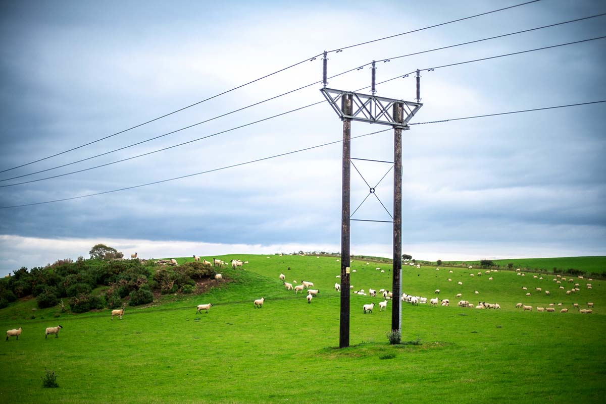
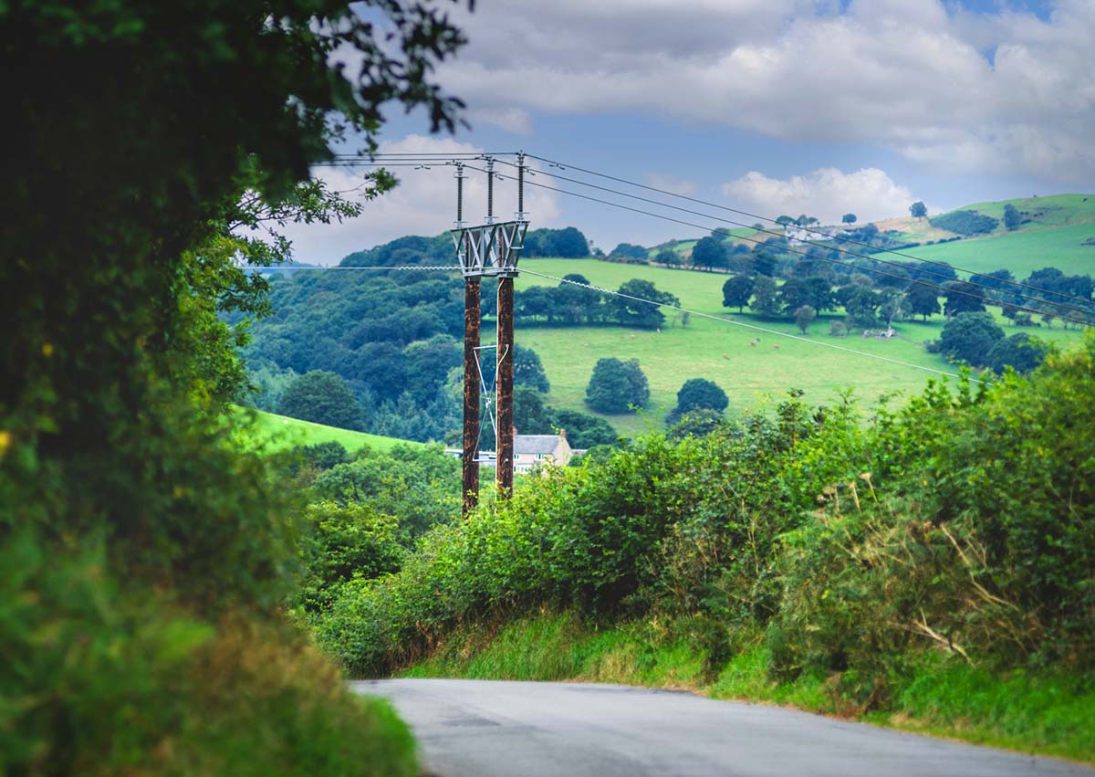

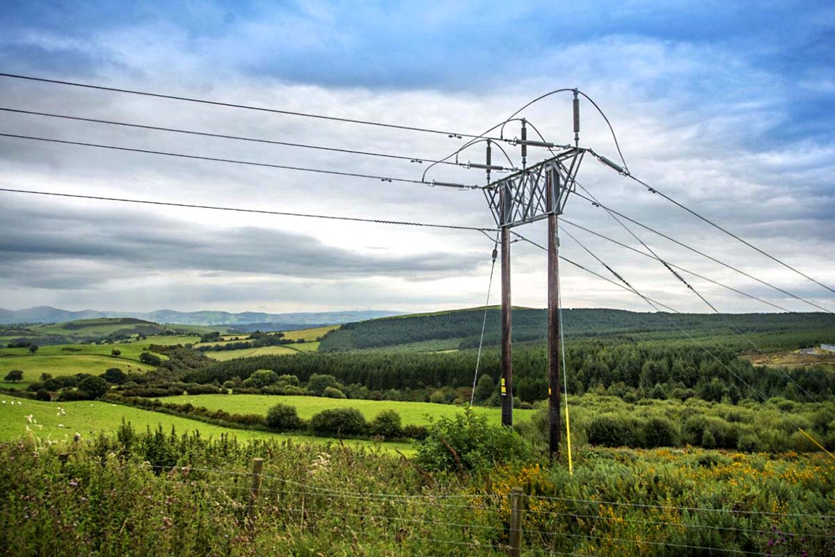
images: Green GEN Cymru
Overhead electricity lines on wood poles are generally used for low voltages, 11, 20, 33, 66 and 132kV . Although 132kV lines can be carried on single wooden poles, double pole "H" designs are favoured. The common description "H" is deceptive as they are more like a Greek letter Pi "Π". The double poles are topped by galvanised steel cross-members of various designs, carrying the insulators that attach the conductor wires.
Pole height varies depending on terrain, typically between 12 and 16 metres but can be up to 24 metres tall. Spacing between poles is variable between 50m and 155m, but on average 100 to 120m. Minimum cable height above ground for up to and including 132kV power lines is normally 6.7m
Pole timbers are most often imported from Northern Europe. They are a softwood, usually pine, and are pressure treated with creosote preservative.
To erect the poles they are dropped into holes made with a soil auger or alternatively narrow, stepped excavations by a digger. The poles are sunk into the ground to variable depths largely dependent on the pole weight and height. A 14 metre heavy-duty pole would typically be sunk up to 2.6m deep. The lighter low voltage poles may be less than 2m deep, whereas tall poles can be up to 3.2m. Foundation blocks or braces may be used. Holes are backfilled and firmly compacted to give a stable base. A soil stabiliser powder is often first mixed with the fill.
Where a line changes direction, stay wires (guy lines) are needed to ensure stability.
During construction a variety of heavy equipment is used, however much of this is fairly commonplace and not especially excessive in size. Access tracks are required, typically a minimum of 3.5m wide, which may be temporary. Also temporary working areas are needed for assembly, equipment and storage. Depending on the local conditions all-wheel drive vehicles may be necessary and for remote, wild terrain it may be preferable to deliver materials to the installation sites by helicopter.
Prior to construction trees must be felled and other tall vegetation cut back to form the required wayleave corridor for the line. A minimum clearance corridor of about 9m is normally needed. This corridor must be regularly maintained for the life of the line.
Although commonly promoted as being acceptable in the landscape, wood pole electricity lines can be major projects and the poles themselves substantial structures, bearing in mind they are typically twice the height of an average two-story house. Although possibly less incongruous in rural areas than steel pylons, the lines are certainly detrimental to natural landscapes.
ADVANTAGES
- Simple, familiar, well understood
- Low technology
- Can use bare metal conductors
- Relatively low cost
- Construction equipment readily available
- Adaptable to difficult terrain
- Visually more acceptable than pylons
- Small ground footprint
DISADVANTAGES
- Maximum 132kV, single circuit
- Temporary access tracks and work areas during construction
- Can cause disruption for landowners
- Greater density of supports than pylons (shorter spans)
- Visual degradation of landscape
- Susceptible to storm damage, tree falls
- Regular checks and maintenance required
Overhead: Metal tower pylons
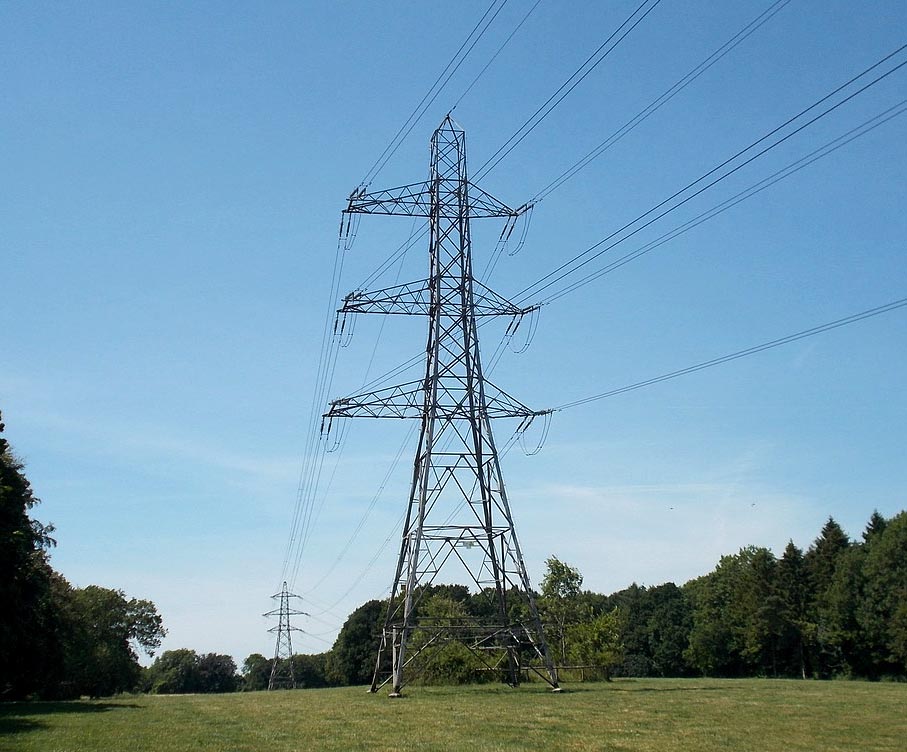
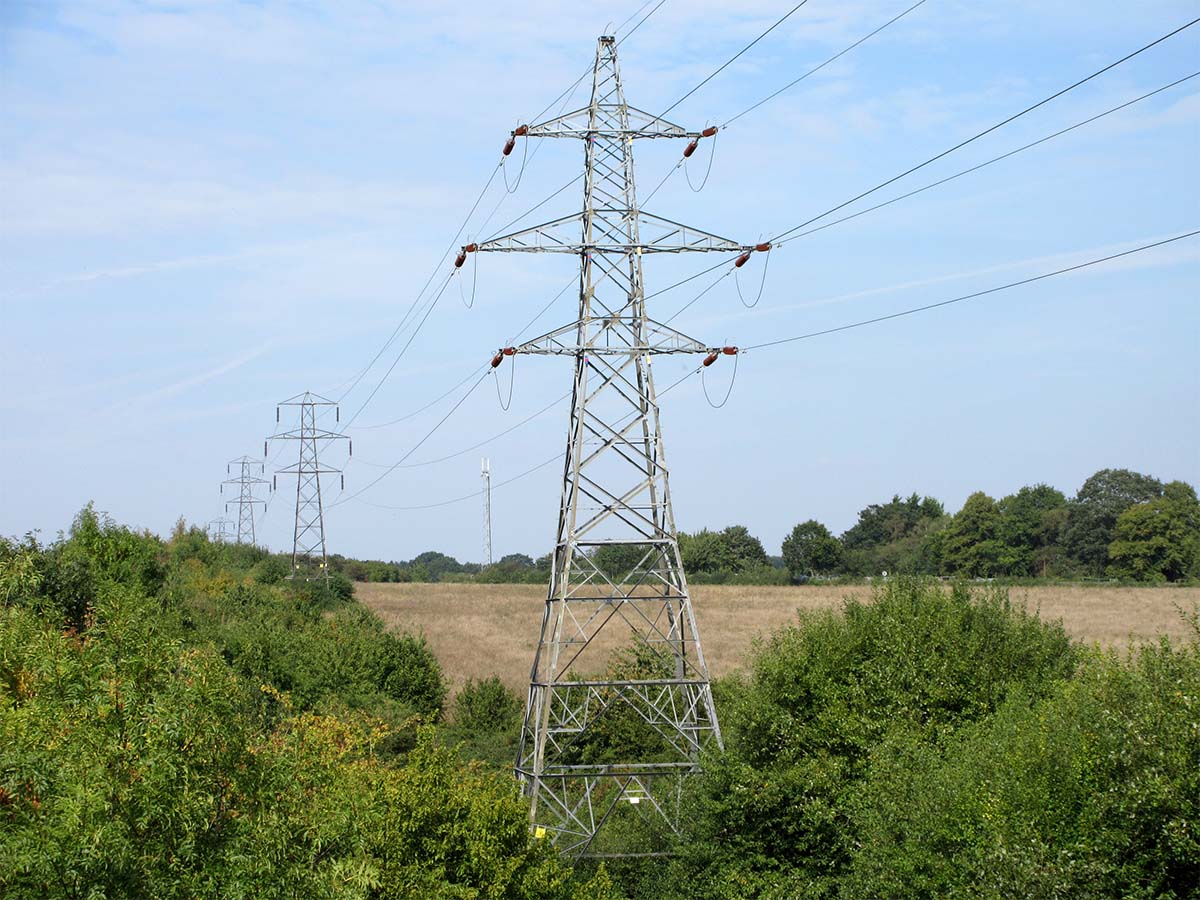
Overhead pylons lines are used for high voltage transmission, 132kV, 275kV and 400kV. There are a number of designs and sizes for steel lattice pylons (aka. transmission towers) and have been in use in the UK since the 1930's. High voltages are used for transmission because it allows reduced current and therefore minimises energy loss, giving greater efficiency especially over long distances.
Steel pylons are specified for the 132kV proposals in Wales because they can carry dual circuits, using six conductor wires. They can also support heavier guage conductors. For the proposed powerlines L7 type pylons will most likely be used. They have a number of different forms and are smaller than those typically used for higher voltages. Their standard height is 27 metres, but can be increased where needed by extensions to 36 metres. Base width is 8.4m and the widest cross arms are 12.6m. Typical span between pylons is 250m, variable depending on the situation. The minimum cable height above ground for 132kV is the same as for wood poles, normally 6.7m, however actual clearance for steel pylons will usually be substantially greater.
400kV transmission lines use larger pylons with a height of around 50m and of generally more heavy duty metalwork.
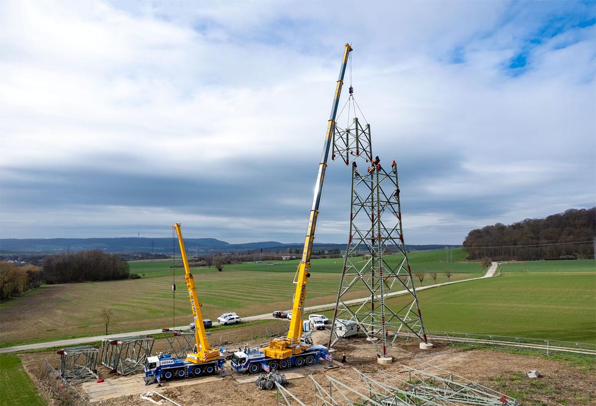
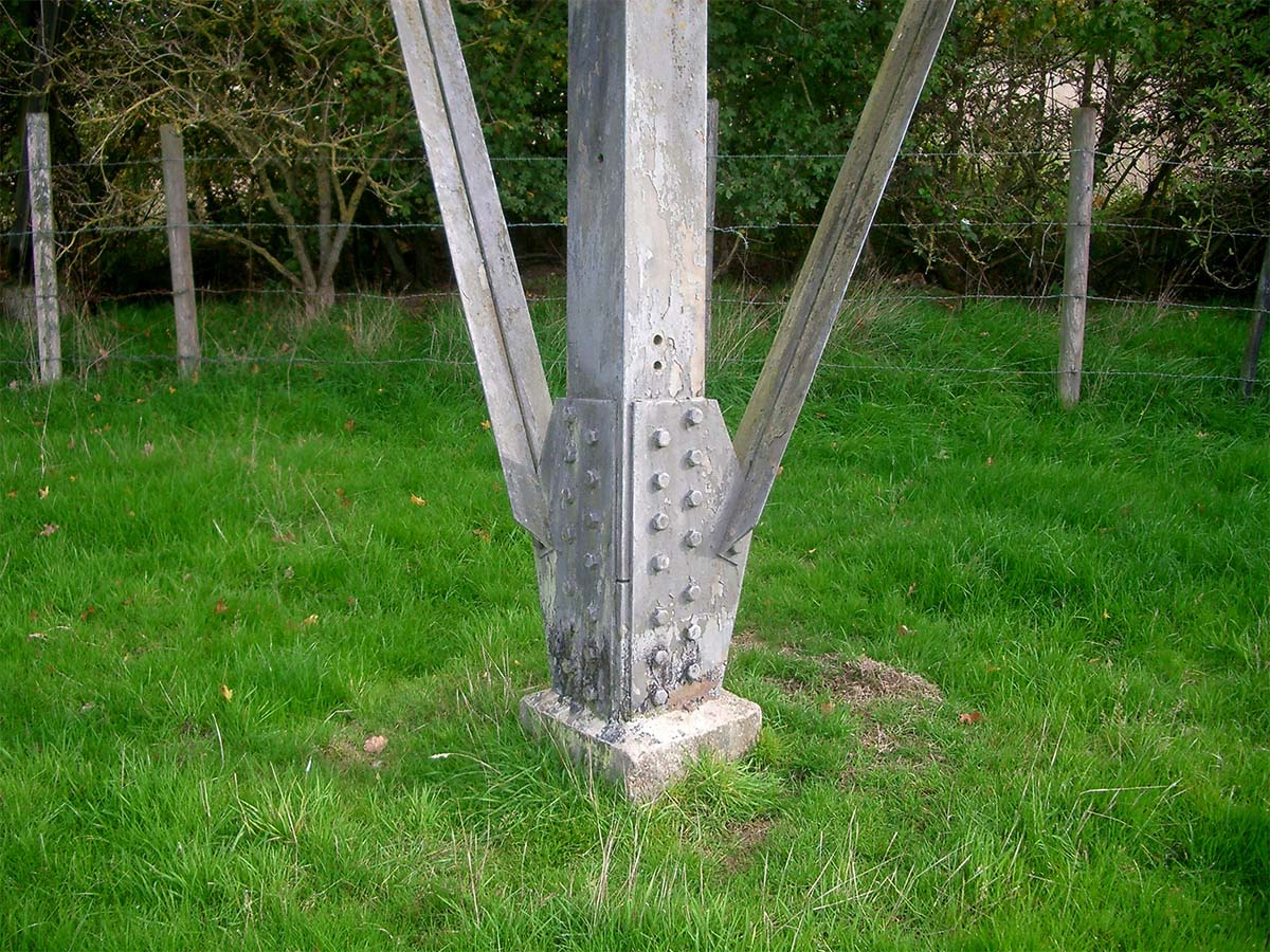
Steel pylons are normally constructed on-site, after delivery in kit form by lorries. Each leg is bolted to a separate concrete foundation. The foundations need to be substantial and usually have a combined weight much greater that the steelwork they support. Each foundation is specified according to the expected loads, resulting in differences between straight line sections and direction changes. The concrete foundations have an angled steel stub to facilitate bolting. As tower sections are assembled they are lifted into position by large cranes.
Once a sequence of pylons has been erected, the conductor wires are fed onto them using winching machines, a process known as "stringing". Where the cables cross public access areas such as roads, protective scaffolding and netting may be needed. The wires are bare metal and attached by ceramic or glass insulators to prevent electricity reaching the steelwork.
Construction requires access roads capable of carrying heavy lorries, cranes and machinery, often including temporary tracks between the pylons. Compounds for assembly work and short-term storage are also needed.
Prior to construction trees must be felled and other tall vegetation cut back along the line corridor and for any access routes. The corridor must be kept clear of tall trees. The pylon sites must remain accessible for inspection and maintenance.
ADVANTAGES
- Simple, familiar, well understood
- Low technology
- Can use bare metal conductors
- Moderate relative cost
- High voltage capacity
- Adaptable to difficult terrain
DISADVANTAGES
- Significant visual impact
- Devaluation of nearby properties
- Large carbon footprint (concrete, steel and transportation)
- Construction time, many weeks or months
- Heavy vehicles and large cranes needed
- Big working area and temporary roadways
- Disruption and loss for landowners
- Susceptible to weather events, lightening, storm damage
Underground: Open Trench
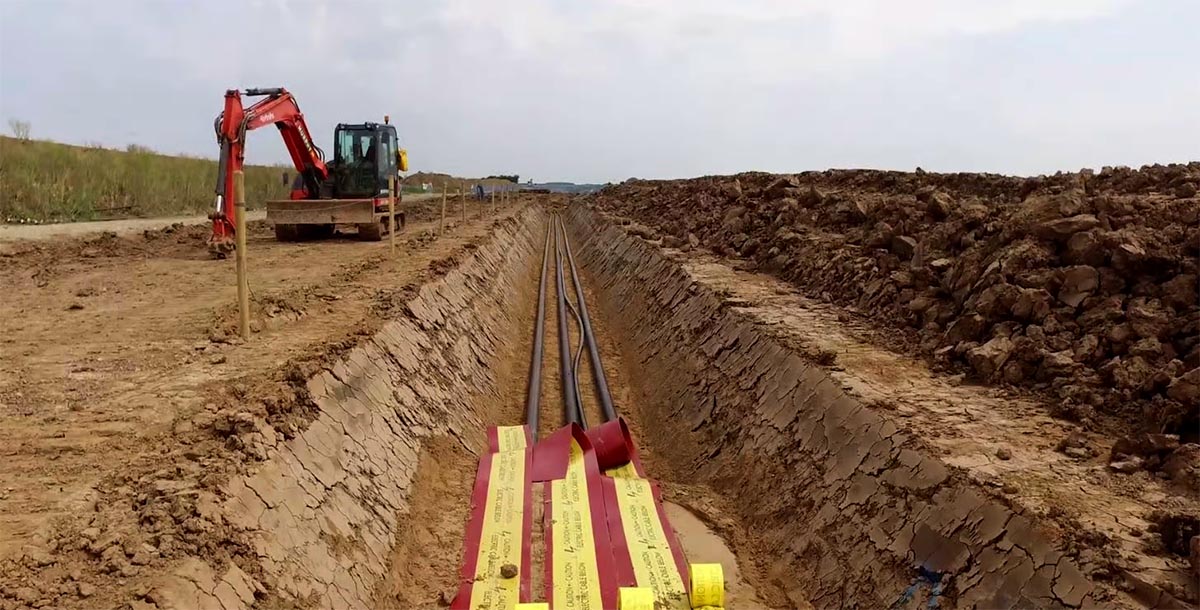
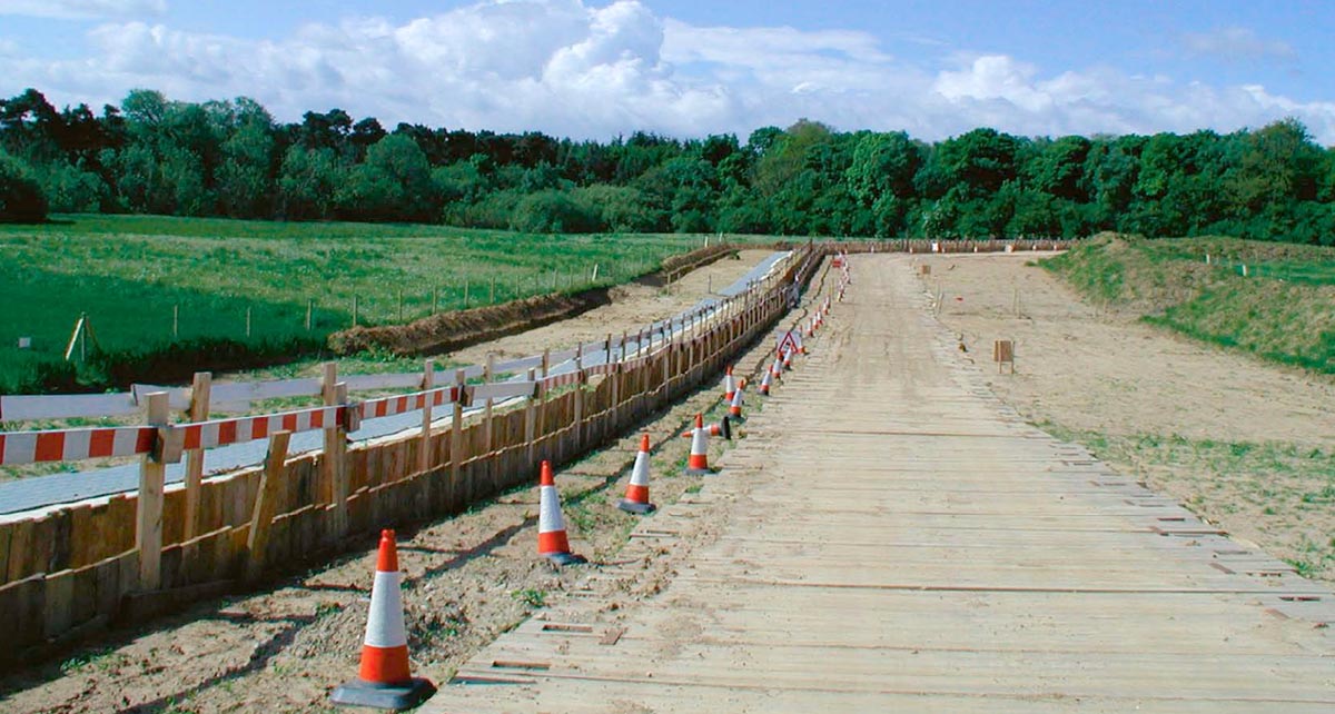
Low voltage underground power cables are commonly used in urban and industrial areas, but less frequently in rural situations and rarely for high voltage transmission. The traditional installation method is by open trench digging. There are two basic variations: either direct buried cables or laying ducts in which the cables are run. Using ducts is more expensive than direct burial but has the benefit of allowing shorter excavation sections and potentially easier future maintenance.
Possibly the biggest technical difference from overhead lines is that the cables must be robustly insulated, making them much more expensive. The insulation must allow for heat dissipation which is more problematic than with air-insulated overhead cables. There are various designs of cable including liquid and gas insulation, but the more recently developed XLPE cables (Cross Linked Polyethylene Extruded) are relatively simple to use and are becoming favoured for most purposes.
Installation is relatively straightforward, although a major operation. Temporary access roads to the working site for machinery may be needed. A large working swathe is required, up to 65m wide and usually fenced off during the work. This is cleared of all vegetation such as trees and hedges, then top soil is removed and stored. The cable trenches can then be dug, normally with separate trenches for each circuit. The trenches are approximately 1.5m wide and 1.2m deep, but can be up to 2m depending on conditions. The cable is then laid in a bed of sand, often cement bound, and carefully compacted around the cable. The trench is then backfilled. When the required number or trenches are completed, top soil can be returned and the surface reinstated as much as possible.
A concrete lined joint bay is needed at approximately 1km intervals. This may be wider than the trench course and future access for maintenance must be ensured.
For certain difficult obstacles, such as main roads or rivers, underground boring by horizontal directional drilling (HDD) may be needed where open excavation is not practical. This requires additional specialist equipment and operators.
During the installation there is inevitably considerable ecological damage. Natural recovery is likely to be slow due to the extent of the excavation. There will also be restrictions on use of the land. As well as the obvious limitations on any deep excavation activity, tree planting within 3m of the trenches is also not allowed.
ADVANTAGES
- No visible impact once completed
- Minimal effect upon property values
- Agricultural land can still be used
- Less susceptible to weather related damage
- Improved electrical safety
- Longer operational life than overhead
DISADVANTAGES
- Large working corridor needed
- Disruption for landowners over many months
- Much greater initial cost
- Requires high quality, insulated conductors
- Construction is environmentally damaging
- Long environmental recovery times
- Some land use restrictions along the line
- Difficult fault finding and repair
- May suffer greater power loss over long distances
Underground: Cable Ploughing
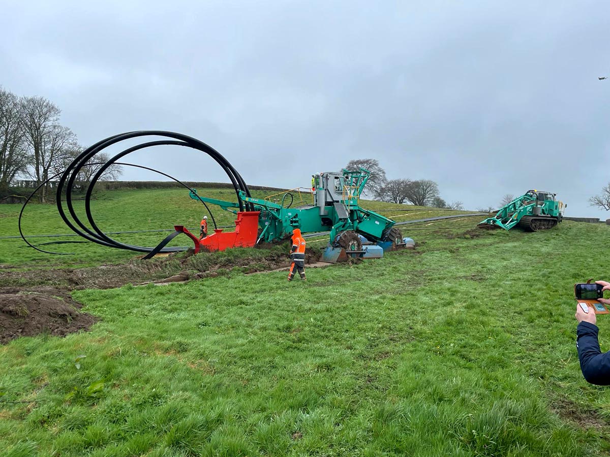
Cable ploughing is an alternative installation method using highly specialised equipment to cut a narrow slit in the ground and feed the cable or conduit duct into it. This is a much faster process than open trenching and does not demand a large working area, therefore offers considerable cost savings. Most significantly, this technique causes far less environmental damage.
The equipment used is purpose-designed for this task and there are relatively few manufacturers. The recognised world leader is Walter Föckersperger who produce the Foeck Spiderplough. They are a family run German engineering company focused entirely on this technology. The plough machine has no driven wheels but is pulled along by an extremely powerful winch vehicle. This enables it to tackle very varied terrain that would be impossible for normal vehicles. The largest machine is able to plough to a depth of 2.5m and can lay conduit pipes of up to 630mm diameter.
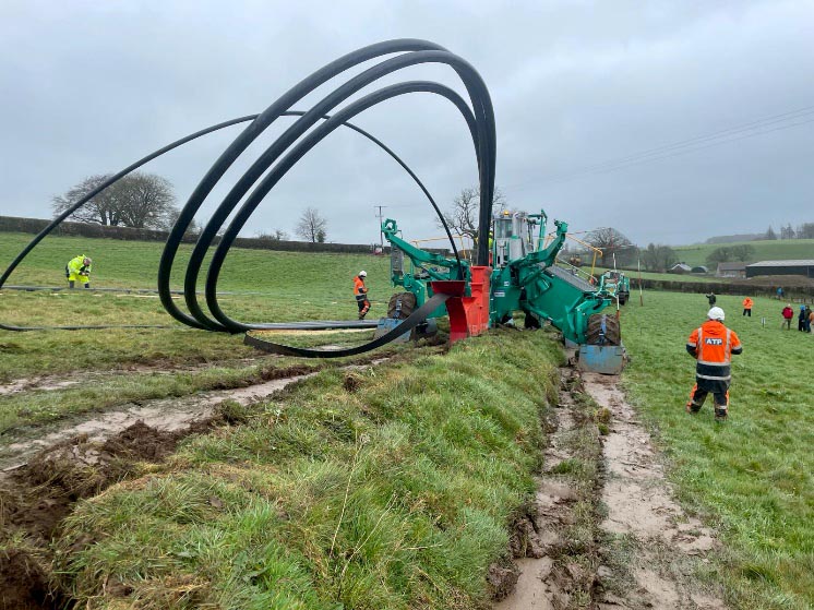
Some prior clearance of vegetation may be needed to enable access for the large machines, but no special roadways or additional working areas are needed. The operating width of the plough is variable between approximately 3 to 6.5m. As the plough moves along it opens a narrow trench into which it lays the cable. If a bedding material such as sand is needed, that can be delivered by a chute into the trench at the same time. It then partly closes the trench. If multiple trenches are required, for example to accommodate separated conductor circuits, then the machine is simply returned to start of the section and a parallel plough run is done.
After ploughing the trench is fully closed and the land reinstated, usually on the same day. The process is very fast and several kilometres of cable can be laid each day. This also minimises the ecological disruption along the cable route and it causes less damage to the surrounding soil structure.
In common with the open trench method, for difficult obstacles such as roads or rivers, horizontal directional drilling (HDD) is used to continue the underground cable route. This requires additional specialist equipment and operators.
Also in common with open trenching, concrete lined joint bays are needed at approximately 1km intervals. These need to be excavated and constructed in the conventional manner and future maintenance access considered. Similar restrictions for land use will apply once the cable laying is completed.
ADVANTAGES
- No visible impact once completed
- Minimal effect on property values
- Speed of operation, land is quickly back in use
- Lower cost than open trenching
- Minimal effect on the environment
- Short environmental recovery times
- Agricultural land can still be used
- Less susceptible to weather related damage
- Improved electrical safety
- Longer operational life than overhead
DISADVANTAGES
- Specialised equipment and expert operators
- Greater initial cost than overhead cables
- Requires high quality, insulated conductors
- Cannot be used for certain terrain conditions
- May encounter unforeseen underground artifacts or historical remains
- Some land use restrictions along the line
- Difficult fault finding and repair
- May suffer greater power loss over long distances
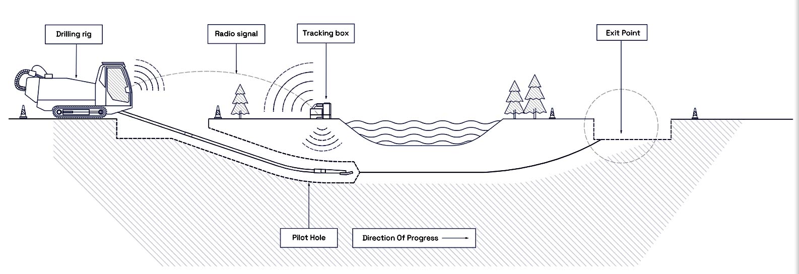
Underground: Horizontal Directional Drilling (HDD)
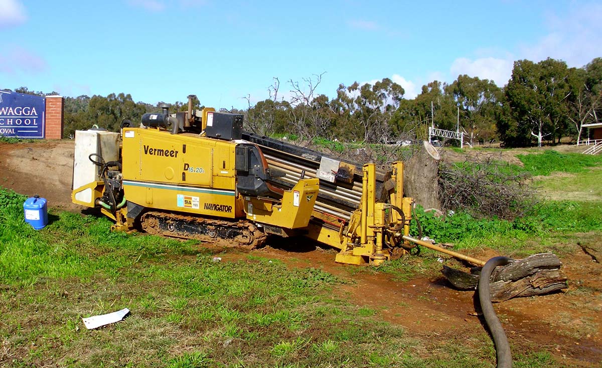
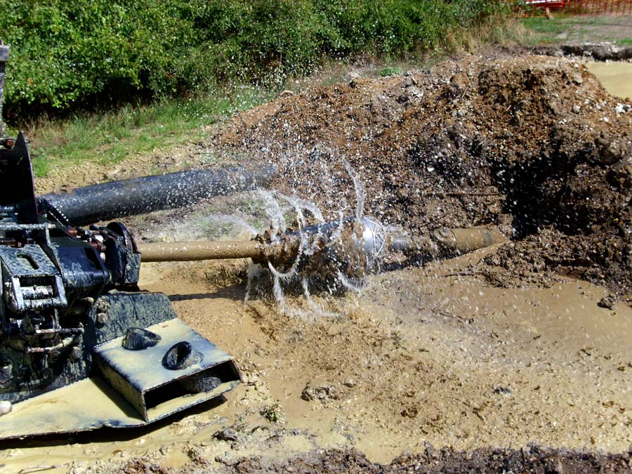
HDD, also known as horizontal boring, slant drilling or just directional drilling, is a trenchless method used to install electrical conduits or other services. Operating from one site to a destination exit point, it has minimal surface disruption and can pass below large obstacles such as rivers or roads.
The process begins with thorough ground planning and surveying which is essential to avoid causing serious damage. A pilot bore is drilled along a carefully designed path. Using advanced locating systems, the drill head is guided underground to avoid obstacles and any existing utilities. Once the pilot bore is complete, the hole is enlarged by a reamer to the required diameter. Finally, the conduit duct pipe is pulled back through the borehole.
Temporary access and work areas are needed for the machinery and storage of materials. Various sizes of drilling equipment are available, from quite small to powerful heavy-duty systems able to handle major tasks.
Permanent junction arrangements of some kind may be required at the entry and exit points of the drilled section.
ADVANTAGES
- Minimal impact on the surface environment
- Little or no visual consequence
- Can traverse major obstacles
- Works well in conjunction with other underground methods
- Same long term benefits as other undergrounding
DISADVANTAGES
- Specialised equipment and expert operators
- High initial cost
- Practical only for relatively short distances
- Needs working area and temporary access roadways
- May require additional connection junctions
- Shares similar long term issues as other undergrounding
Summary
Due to familiarity and relative lower initial cost, overhead lines are more attractive to investors and shareholders.
All options are damaging to the environment to some extent, from a little to a lot.
Overhead lines are visually intrusive in the landscape with metal structures especially unacceptable in rural and wild places.
Wood poles attract less attention, but heavy-duty and double poles are not much better than steel pylons.
Underground cables are not as susceptible to bad weather events.
Underground cables are safer and have fewer failures, but when faults occur they can be harder to fix.
Planning and installing underground cables is generally more difficult than overhead.
Expert skills and modern technology can make underground installation faster, less ecologically damaging and reduce costs.